
Technical
These documents are available as PDF files - simply click on your choice of U.S. or Metric Units.
Isolators can be modeled explicitly in analysis software such as ETABS, SAP2000 and LARSA. When software does not support an explicit isolator element, a spring element or a short column may be used to simulate the isolator.
The behavior of a lead rubber bearing is modeled as a bilinear hysteretic element, with an initial stiffness
(Ke), yield force (Fy) and secondary stiffness (K2 or Kd).
For response spectrum analysis the effective stiffness (Keff) and the equivalent viscous damping which is derived from the isolator's EDC (energy Dissipated per Cycle) are required.
For nonlinear time-history analysis, the bilinear properties of the isolator (initial stiffness Ke, yield force Fy,
and the secondary stiffness K2) are used. The vertical stiffness of the isolators is also required as part
of the element description. An interesting characteristic of elastomeric isolators is that the compression stiffnes is about 100 times the tensile stiffness. Care must be taken in modeling the vertical stiffness to ensure the accuracy of the analytical results.
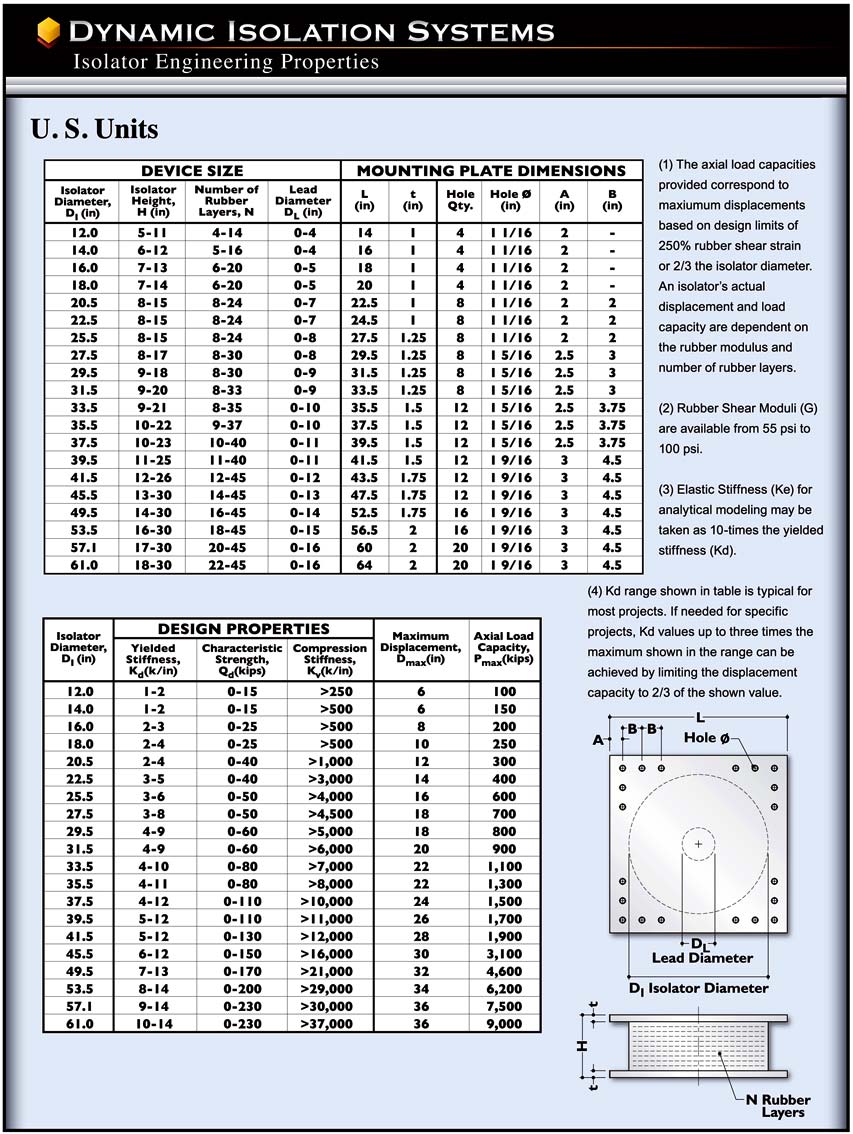
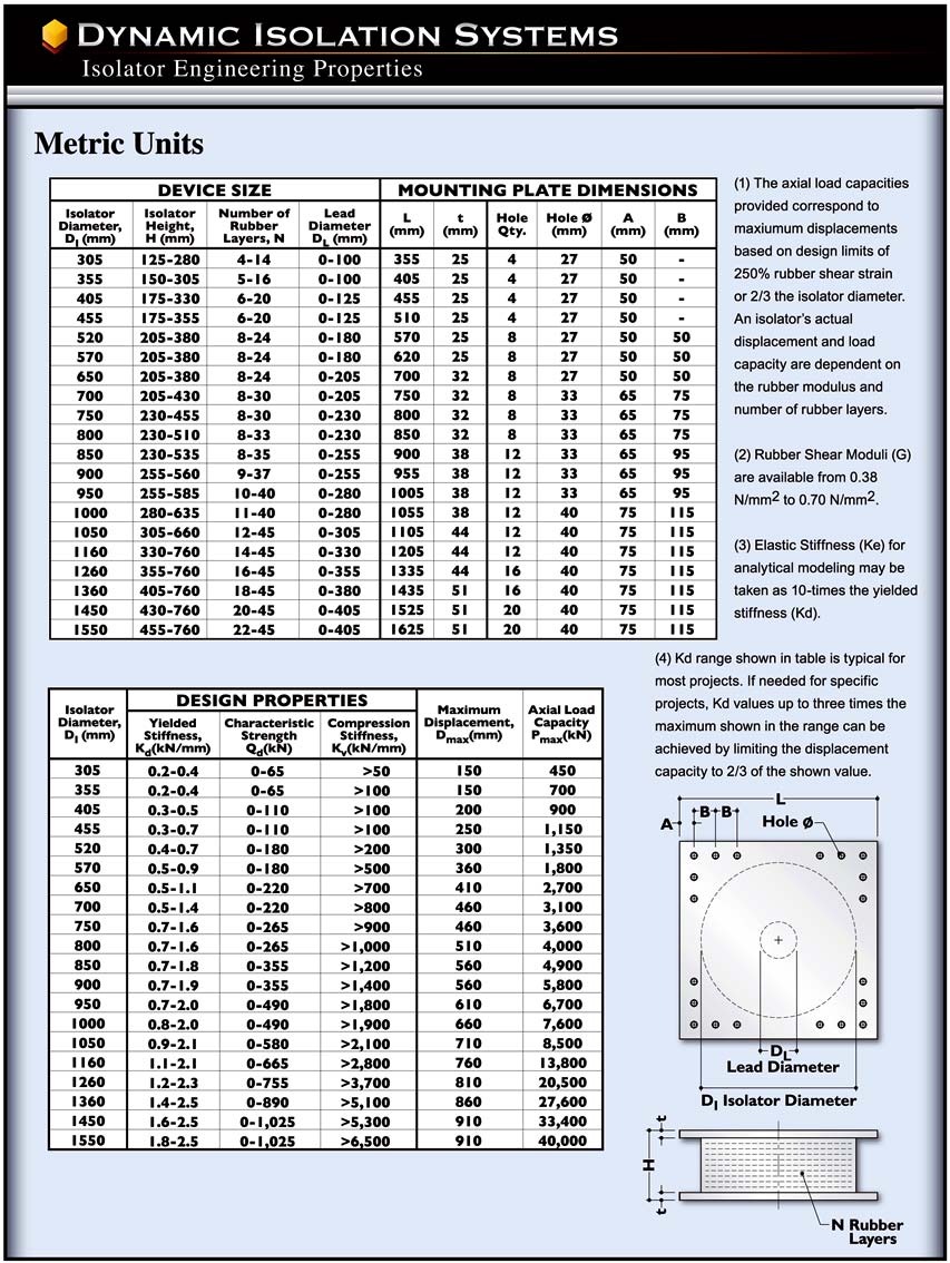
Typical values of these parameters for a wide range of DIS isolators are shown in the Isolator Properties Tables.
DIS can provide specific modeling parameters and assist with the fine tuning of the isolation system
throughout the design process.
(Ke), yield force (Fy) and secondary stiffness (K2 or Kd).
For response spectrum analysis the effective stiffness (Keff) and the equivalent viscous damping which is derived from the isolator's EDC (energy Dissipated per Cycle) are required.
For nonlinear time-history analysis, the bilinear properties of the isolator (initial stiffness Ke, yield force Fy,
and the secondary stiffness K2) are used. The vertical stiffness of the isolators is also required as part
of the element description. An interesting characteristic of elastomeric isolators is that the compression stiffnes is about 100 times the tensile stiffness. Care must be taken in modeling the vertical stiffness to ensure the accuracy of the analytical results.
Typical values of these parameters for a wide range of DIS isolators are shown in the Isolator Properties Tables.
DIS can provide specific modeling parameters and assist with the fine tuning of the isolation system
throughout the design process.
Isolator Testing
The United States codes require testing on each project. Prototype tests validate the isolator properties over the range of the project's loads and displacements. Prototype testing may be eliminated due to similarity with previous projects. Production tests check the properties of isolators under the project's load and displacement conditions.
For Japanese projects, extensive testing was performed on different isolators over a wide range of
stresses and strains. This pre-qualification testing eliminated prototype testing for individual pro-
jects. Only QC testing is done on production isolators which reduces cost and shortens schedules
by as much as three months.
stresses and strains. This pre-qualification testing eliminated prototype testing for individual pro-
jects. Only QC testing is done on production isolators which reduces cost and shortens schedules
by as much as three months.
Isolators are tested in pairs at our plant and individually at laboratories such as the
University of California, San Diego (UCSD). The test machine applies a shear dis-
placement and axial load to the isolator. The loops shown plot the shear force and
lateral displacement for the isolator and show the behavior of the isolator for a
range of strains up to 300%.
Real Time Testing
DIS has tested over 30 isolators at actual earthquake velocities of up to 60 inches per second.
The tests were performed at the University of California, San Diego. These tests validate the
performance of our isolators under seismic conditions and provide detailed velocity data for the isolators. Over 500 high-velocity tests have been performed over the last ten years on isolators of up to 53.5 inches (1300mm) in diameter.
Large Strain Testing
DIS has conducted extensive high-strain testing on isolators up to 53.5 inches (1300mm) in diameter. Isolators with and without lead cores have been successfully tested to over 400% shear strain.
Typical design shear strains are in the 200 - 250%
range. Other notable large displacement tests
performed by DIS include a 45.5" (1158mm)
diameter isolator that was tested to 45" (1143mm)
displacement for the Berry Street Project in
California.
One-Mile Wear Test
A one-mile (1.6 km) wear test was performed on DIS isolators at the NEES Lab, SUNY at Buffalo. The tests were conducted as part of prototype testing for the new Woodrow Wilson Bridge over the Potomac River in Maryland. This test simulated the effect of a lifetime of thermal expansions and contractions of the bridge deck. The results pictured here show that the isolator's properties were unchanged by this extreme testing.
A one-mile (1.6 km) wear test was performed on DIS isolators at the NEES Lab, SUNY at Buffalo. The tests were conducted as part of prototype testing for the new Woodrow Wilson Bridge over the Potomac River in Maryland. This test simulated the effect of a lifetime of thermal expansions and contractions of the bridge deck. The results pictured here show that the isolator's properties were unchanged by this extreme testing.
Terms and Symbols
Click here for a printable version of this page
Hysteresis Loop: This is the force displacement plot generated by the shear testing
of an isolator.
Elastic Stiffness, Ke: This is the initial stiffness of the isolator, typically at less than
one inch displacement. Its value is dominated by the lead core size and is important in
controlling the response to service loads such as wind.
Yielded Stiffness, Kd or K2: This is the secondary stiffness of the isolator and is a
function of the modules, total height and area of the rubber.
Hysteretic Strength, Qd: This is the force axis intercept of the isolator hysteresis
loop. This parameter relates to damping and isolator response to service loads.
Keff (Effective Stiffness): This is the isolator force divided by the displacement.
This is a displacement-dependent quantity.
Yield Force, Fy: The yield force is the point in the model at which the initial stiffness changes to secondary stiffness. In reality, there is a smooth transition from one
stiffness to the other, rather than a well-defined point. This value is mainly used in analytical modeling.
Energy Dissipated per Cycle, EDC: This is the area of the hysteresis loop. This value is a measure if the damping of the isolator.
Vertical Stiffness (Kv): This is the vertical stiffness of the isolator.
DBE (Design Basis Earthquake): DBE represents the ground motion that has a 10% chance of being exceeded in 50 years.
MCE (Maximum Considered Earthquake): MCE is defined as the ground motion that has a 2% probability of being exceeded in 50 years.
Frequently Asked Questions
What does shear strain refer to?
The shear strain is the isolator lateral deformation divided by the rubber height. Design shear strains are up to 250%. DIS has tested isolators to more than 400% shear strain. At that strain, each layer of rubber is deformed laterally to four times its thickness. The extreme shear strains in research tests are a testament to the superior manufacturing processes and compounds developed by DIS and provide the isolator with reserve capacity.
What are typical design displacements?
In high seismic zones such as San Francisco, Tokyo and Istanbul the isolator displacements are up to 30inches (762mm). For structures located further from faults or on better soil the isolator displacements are up to 20 inches (500mm). In low seismic zones such as the eastern United States, movements are in the range of 2 to 6 inches
(50 to 150mm). DIS has tested isolators to 47 inches of lateral displacement and provides isolators for all seismic zones worldwide.
How is the period of the structure shifted?
The fundamental period of the structure is shifted by the addition of flexible
isolators. The isolated period is generally more than 2 seconds. The
dominant frequencies of an earthquake are in the 0.2 to 0.6 second range.
The severe accelerations of an earthquake are avoided due to the period
shift provided by isolation (See Diagram 1).
How is displacement controlled?
The isolator displacement is decreased by increasing its stiffness or
damping. The design trade-off is that forces and accelerations increase as
the displacement is decreased.
How does added damping benefit the structure?
Damping absorbs earthquake energy. The addition of damping reduces the
displacements and forces in the superstructure by as much as 50%
(See Diagram 2).
What is the suggested level of damping in an
isolation system?
Most structures have 2-5% inherent damping. Isolation systems for bridges typically provide damping levels from 15 to 30%. Isolation systems for buildings have
damping in the 10 to 20% range. The building damping levels are optimized to provide low accelerations in the structure which maximize content protection.
What is the difference of the lead core yield strength at creep loads and earthquake loads?
The hysteretic behavior of lead is dependent on the rate of loading. The yield strength is lower at creep velocities than at earthquake velocities. This is beneficial
especially in bridges where the isolator moves over a range of velocities. During the high-velocity seismic motion, the yield stress ranges from 10 to 14 MPa. providing significant levels of damping. For thermal movements, the yield stress is in the range of 4 to 6 MPa, which imposes small forces on the structure. Intermediate
values of lead stress resist service loads such as wind and braking.
What is the design of the life of the bearings?
The normal design life of the bearing is over 50 years. Elastomeric pads in highway bridges have
been in use for over four decades exhibiting good durability. Isolators with modern rubber
formulations surrounded by a protective cover rubber are expected to be more durable and stable
in their long-term performance.
Plotted here are the responses of an isolator over a range of velocities from one cycle
in a
day to one cycle in 12 seconds. The lead force at low velocity is 60% of that at high velocity.
day to one cycle in 12 seconds. The lead force at low velocity is 60% of that at high velocity.
Does the structure re-center after an earthquake?
A structure re-centers after an earthquake because a restoring force is provided by the rubber. The shaking characteristics also make the structure oscillate at ever-decreasing displacements about its original position as the earthquake motion subsides. The Eel River Bridge in California re-centered after a magnitude 7.0 earthquake
to within a 1/4-inch of its original position.
What is the response to the vertical component of an earthquake?
Isolators are stiff in the vertical direction and do not change the vertical seismic response. The vertical component of the earthquake results in axial load variations which
can be accommodated in the design of columns and the isolators. Shake table tests have been conducted with and without the vertical component of the earthquake motion. The results indicate that there is very little difference in their performance of the isolators.
Can a tall building be isolated?
Tall buildings such as the 18-story Oakland City Hall in California (left) have benefited from isolation. Buildings normally require the isolated period to be 2.5 to 3 times that of the non-isolated building. There are many tall buildings isolated in Japan that have an
isolated period in the range of 4 to 6 seconds. The designers chose isolation for the better performance that it provides.
Does the lead core fatigue?
Lead is in its elasto-plastic phase at ambient temperature. As with other metals in this phase, lead re-crystallizes rapidly after being deformed without fatigue.
Can an isolator resist tension forces?
An allowable tensile stress of up to 50 psi can be applied to an isolator. The actual allowable stress depends on the displacement
of the isolator and the rubber modulus. In general, tension is avoided in design.
Can more than one bearing be use under a column?
Multiple isolators have been used on San Francisco City Hall and the Tan Tzu Medical Center in Taiwan. Multiple isolators are used when they are more economical than one larger, single isolator.
How are elevators accommodated?
The bottom section of the elevator is suspended from the superstructure of the building. The framing cantilevers down and is not supported by the substructure. Alternately the plane of isolation can be lowered several feet locally to allow the elevator pit to be isolated as part of the superstructure.
How are stairways detailed?
Stairways and access points are detailed to be fixed to the superstructure and be "simply supported" on the structure below the isolators. Small sliders are sometimes used to support stairs and accommodate lateral movements.
How do utilities accommodate movement across the isolation plane in the buildings?
Utilities that cross the seismic plane must be detailed to move horizontally. They often are made to be flexible or are fitted with universal joints (right).
What are the fire protection requirements for base isolators?
Out of more than 300 projects only three have required passive fire protection due to being in a space with a fire load. The need for fire protect-ion is determined by either the Fire Marshall or the Fire Engineer. Ninety-nine percent of our projects have not required fire protection as shown in this photo of The Berkeley Public Safety Building in California (left).
In cases where fire protection was required the most cost-effective method was to use fire-rated board materials over metal framing (middle right).
The cost of this type of fire-rated enclosure is in the cost range of a few hundred dollars.
The joint between the two sections is sealed with a simple intumescent seal.
Fire blankets (left) have also been used. DIS recommends the board-type solution as it is
generally more economical and is installed by on-site carpenters as part of the regular framing work.
Are isolators "fire-rated"?
Some isolation manufacturers have made claims that their product is "fire-rated". Such statements are not supported by any building code and would need to be proven by testing in accordance with ASTM E119.
Some isolation manufacturers have made claims that their product is "fire-rated". Such statements are not supported by any building code and would need to be proven by testing in accordance with ASTM E119.
DIS engaged Holmes Fire LP to assess such claims. Their findings are summarized below:
The code requires no rating of isolation systems in certain circumstances. Generally this is
due to the absence of any fire load, as is typical in a basement.
An isolator needs to be tested by a Nationally Recognized Testing Laboratory (NRTL) to determine its
compliance with a code. (DIS's understanding is that no isolation product meets
or can meet this
requirement).
A fire engineering assessment can rationalize or eliminate the need for fire protection.
Holmes' full report can be found in the PDF attached to this link. We recommend that the Architect or the
project's Fire Consultant review Holmes Fire's assessment of code compliance.
Privacy Policy | Terms and Conditions
| Copyright © 2019 Dynamic Isolation Systems, Inc.
Site Design by www.KUcreative.com | Developed & Maintained by www.cidmedia.com
Site Design by www.KUcreative.com | Developed & Maintained by www.cidmedia.com